Minimum size
Probably at least 20cm for most work. Some brighter targets can be worked with
something a little smaller.
Good mount
Perfect optics are of no use on a mount that can’t track or go where you tell it. Most of today’s automated telescopes are great for getting
you close to the target. You may have to work on the tracking to get it so you can take 1-3 minute unguided exposures. Guided imaging is fine but usually
complicates matters. If you can get the mount to track adequately for 1-3 minutes, you’re going to be able to work targets that provide enough signal to
get good results. If you have to guide for 5 minutes, you may get better data but then the asteroid may move a significant amount or, if it’s rotating
relatively fast, loose critical data by undersampling the lightcurve.Besides proper balancing and fine-tuning the mechanics, never under estimate the
value of good polar alignment. Work on that but don’t get obsessed with it. I’ve
seen some news group discussions where people were concerned about moving the
mount small fractions of a millimeter. Lightcurve work can tolerate something less than those trying to get “perfect pretty pictures” might accept.
Click here for some good polar alignment outlines.
Needless to say, you’ll get a lot more work done with less effort if you have a
permanent setup. Even if you can’t build a full-blown observatory, at least try
to have your pier/tripod and wedge (assuming an SCT) in a permanent setup so that all you have to do is put on the scope and get started. It’s even better if
you can build an inexpensive “dog house” or “flip lid” observatory. u Automation. With today’s equipment and software, there’s very little reason
for you to be up all night. Take advantage of what’s available and get your
system to where you can start a script or other automation process to get all your images without you being at the scope or computer all the time. You’ll be a
much happier (and rested) person!
Pixel Size
It’s important to match the scale of your images to your average seeing. The old rule of two arc-second pixels is a generalization that
assumes your average seeing is about one arc-second. I should be so lucky! The proper rule is that the pixels should be about one-half the average FWHM seeing.
So, if your average seeing is four arc-seconds, then you want pixels of about two arc-seconds.
You can compute the pixel size by
Scale = 206265 / F * W
Where F is the focal length of your system and W is the size of the pixel in millimeters. For example, at the Palmer Divide Observatory, the main scope has a focal length of 162” and the camera has pixels of 0.024mm (24 microns).
Scale = 206265 / 4115 * 0.024
This gives a value of about 1.2 arc-seconds. Unfortunately, my seeing is not on the order of 2-3 arc-seconds but closer to four to five. I usually bin the camera 2x2, which gives me 2.4 arc-second pixels and more closely matches my seeing. On a rare night of better seeing, I can use the 1x1 pixels.
Here’s a table that gives some common examples of focal length and pixel size combinations.
|
|
|
|
|
|
|
FOV |
FOV |
FOV 20 |
FOV 24 |
|
40 |
203.0 |
1.42 |
1.83 |
4.06 |
4.87 |
51.73 |
23.30 |
34.65 |
83.16 |
|
60 |
135.3 |
0.94 |
1.22 |
2.71 |
3.25 |
34.49 |
15.53 |
23.10 |
55.44 |
|
80 |
101.5 |
0.71 |
0.91 |
2.03 |
2.44 |
25.86 |
11.65 |
17.32 |
41.58 |
|
100 |
81.2 |
0.57 |
0.73 |
1.62 |
1.95 |
20.69 |
9.32 |
13.86 |
33.26 |
|
120 |
67.7 |
0.47 |
0.61 |
1.35 |
1.62 |
17.24 |
7.77 |
11.55 |
27.72 |
|
140 |
58.0 |
0.41 |
0.52 |
1.16 |
1.39 |
14.78 |
6.66 |
9.90 |
23.76 |
|
160 |
50.1 |
0.35 |
0.45 |
1.00 |
1.20 |
12.77 |
5.75 |
8.56 |
20.53 |
Anti-Blooming vs. Non AB Chips
Anti-blooming is a technique that prevents individual pixels from being over-saturated by draining off excess electrons.
This makes for nicer looking pictures when bright stars are in the image because
you don’t see the familiar “chimney pipe” effect – that long vertical streak
above and below a star. The downside of this for photometry is that the pixel value no longer represents the actual number of photons that hit the pixel. The
response is no longer linear. Another issue is that some ABG cameras are about 30% less efficient at collecting photons, meaning that for a given exposure an
ABG camera is not going to go as faint as an NABG (non anti-blooming gate) camera.
Usually the draining effect starts around the point where a pixel is at 50% saturation. This means that if you keep your critical objects, i.e., the comparison stars and target, below this point, you can still use an ABG (anti-blooming gate) camera for photometry. However, there is still that loss of efficiency.
The NABG cameras don’t siphon off electrons and so you quite often see the chimney pipe effect. While not so good for pretty pictures, the gain in efficiency and the much wider range of linearity are of considerable value to good photometry.
Front-illuminated versus Back-illuminated CCD Chips

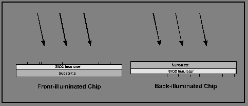
The figure above shows the two basic ways CCD chips are constructed. On the left, is a front-illuminated chip. Here, the incoming light strikes the gates. These are the tiny blocks on the SiO2 insulation layer that are required for creating the charge that allows the device to convert photons into electrons. The problem is the photons must pass through these gates before they can be converted to electrons. The gates act as a mask, particularly in the blue regions where they are often opaque.
On the right is a back-illuminated chip. While the light must pass through the
substrate, the substrate is usually much thinner than for the front-illuminated chip. The main point, however, is that the photons do not have to pass through
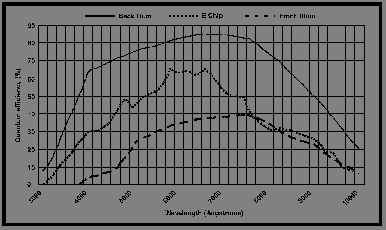
the gates. As you might guess, the back-illuminated chip is more sensitive than the front-illuminated chip. This is quite apparent in the figure below where the
back-illuminated chip has a much high quantum efficiency, i.e., more of the photons that hit the chip are converted to electrons.

From this, you might presume that there is no reason not to get a
back-illuminated chip camera. You’d be right but, once again, nothing is free and certainly not back-illuminated chip cameras, which can be considerably more
expensive than a camera with a front-illuminated chip of the same size and pixel
count. Of a more technical concern is that the substrate holding the pixels in a
back-illuminated camera is much thinner. This adds complications to the manufacturing process so that the substrate doesn’t warp – one of the reasons
for the additional cost. This thinned substrate introduces an effect of fine interference pattern lines in the image, especially in the red and infrared
bands since this is where the chip is most efficient. This fringing is difficult
to remove using flat-fields but can often be handled by introducing an IR blocking filter into the system.
My experience with front- versus back-illuminated chips has not matched the claims by some of one-half to one full magnitude gain using the back-illuminated chips. However, as the old line goes, “your mileage may vary.” If you can afford the cost, including the extra IR filter, I would recommend the back-illuminated chip camera. However, you must factor in all other considerations. If faced with the option to get a back-illuminated camera or one with a blue enhanced chip (see the next section) that’s twice the size and about the same price, I’d definitely go with the larger chip. That’s me. You have to decide what’s right for you.